An adjustable DC power supply is one of the most versatile tools on any electronics workbench. Whether you’re testing a circuit, powering a device, or characterizing components, knowing how to use it correctly is essential.
If you’ve just unboxed one and are wondering, “What do all these knobs and terminals do?”—this guide is for you. We’ll walk you through the basic operation, from initial setup to advanced functions, ensuring you can use your power supply with confidence and safety.
Understand the Key Controls and Terminals
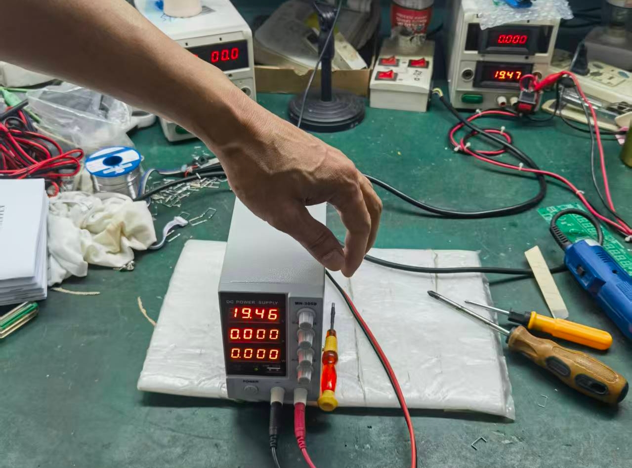
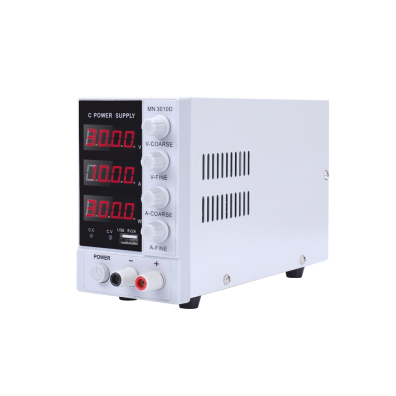
Before you plug anything in, familiarize yourself with the front panel of your adjustable DC power supply. You will typically find:
- VOLTAGE (V) Knob: Sets the desired output voltage level.
- CURRENT (I) Knob: Sets the current limit.
- Output Terminals: The positive (+), negative (-), and often a ground (GND) terminal.
- Digital Displays: Show the set voltage/current and the actual output values.
- OUTPUT On/Off Button: Engages or disengages the output.
- CV/CC Indicators: Lights that show if the supply is in Constant Voltage (CV) or Constant Current (CC) mode.
Step-by-Step: Your First Safe Power-Up
Follow these steps to power a simple device like an LED strip or a microcontroller board safely.
Step 1: Initial Setup (Before Connecting)
- Turn the VOLTAGE and CURRENT knobs fully counter-clockwise (to zero).
- Ensure the OUTPUT button is off.
- Plug the power supply into the wall outlet.
Step 2: Set the Current Limit (Crucial Safety Step!)
This prevents damage to your connected device.
- Short the Output Terminals: Use a lead to connect the positive (+) and negative (-) terminals together.
- Turn on the OUTPUT. The CC (Constant Current) indicator should light up because the short circuit draws maximum current.
- Adjust the CURRENT Knob: Slowly turn the knob until the display shows your desired current limit (e.g., 100mA for a small LED).
- Turn off the OUTPUT and remove the short circuit.
Step 3: Set the Voltage
- Adjust the VOLTAGE knob to your desired level (e.g., 5V for an Arduino, 12V for a fan).
- Double-check that the display shows the correct voltage.
Step 4: Connect Your Device and Power On
- Connect your device to the terminals: positive to positive, negative to negative.
- Press the OUTPUT button. The CV (Constant Voltage) indicator should light up, meaning the supply is providing the set voltage.
What if the CC light turns on instead?
This means your device is trying to draw more current than your limit. The power supply has automatically protected your device by reducing the voltage to stay at the current limit.
Understanding CV vs. CC Mode
This is the core concept of using an adjustable power supply:
- Constant Voltage (CV) Mode: This is the normal operating mode. The supply maintains your set voltage, and the device draws whatever current it needs (as long as it’s below the current limit). The CV indicator is lit.
- Constant Current (CC) Mode: The supply maintains your set current limit because the load is demanding too much. This happens during a short circuit, when powering up a large capacitor, or if the current limit is set too low. The CC indicator is lit.
- Rated voltage:15V/30V/60V/100V
- Full 4-digit display for both voltage and current
- Real-time power display
- Automatic crossover between Constant Voltage (CV) and Constant Current (CC) modes
- Low ripple and noise
- Minimum resolution of 0.01V and 0.01A
- Excellent dynamic response time of <10ms
- Overshoot-free startup with input surge protection
- Intelligent temperature-controlled fan adjusts speed based on load
- Protection features: Over Voltage (OVP) / Over Current (OCP) / Over Temperature (OTP) / ShortCircuit (SCP)
- Standard equipped with USB fast-charging
Practical Applications and Tips
- Testing and Debugging Circuits: Use the current readout to measure power consumption. A sudden, unexpected high current draw indicates a short circuit somewhere in your project.
- Charging Batteries: For simple charging (like Li-ion), you can use CC/CV charging. Set the current limit to the safe charge rate (e.g., 0.5A), and the voltage to the battery’s full voltage (e.g., 4.2V). The supply will start in CC mode and automatically switch to CV when the battery is nearly full.
- Simulating a Battery: Test how a device behaves under different battery levels by simply adjusting the voltage.
- Using the Ground Terminal: Connect the GND terminal to earth ground when you need to eliminate noise or create a common ground reference with other instruments like oscilloscopes.
Essential Safety Tips
- Always Set a Current Limit: Treat this as a mandatory step for every use.
- Double-Check Polarity: Reverse polarity can instantly destroy sensitive components.
- Don’t Exceed Ratings: Never draw more voltage or current than your supply or connected device can handle.
- Beware of Hot Surfaces: Linear power supplies can get very hot during use.
Conclusion
Mastering your adjustable DC power supply is a fundamental skill that will elevate your electronics work. By following this guide—starting with setting a current limit, understanding CV/CC modes, and applying it to practical tasks—you will move from a novice to a confident user. This versatile tool will become your best friend for testing, debugging, and powering all your future projects.